
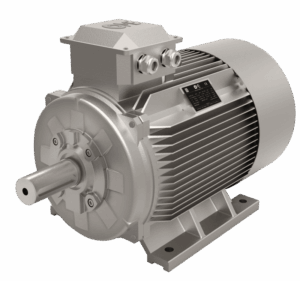
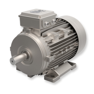
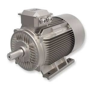
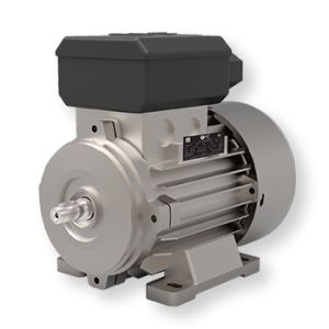
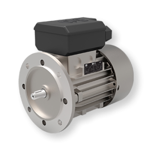
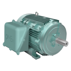
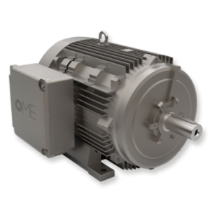
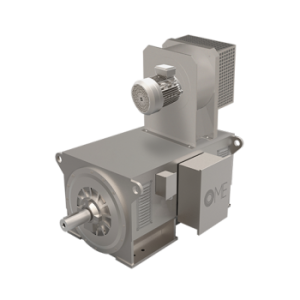
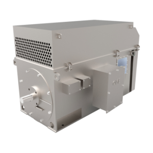
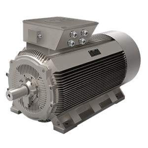

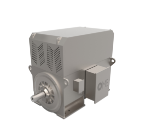
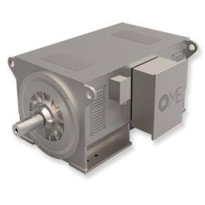
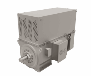
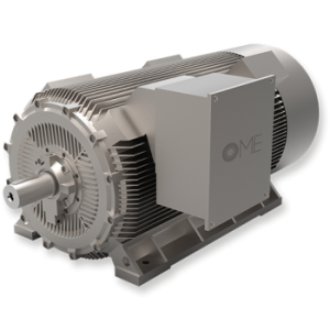
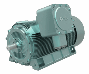
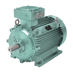
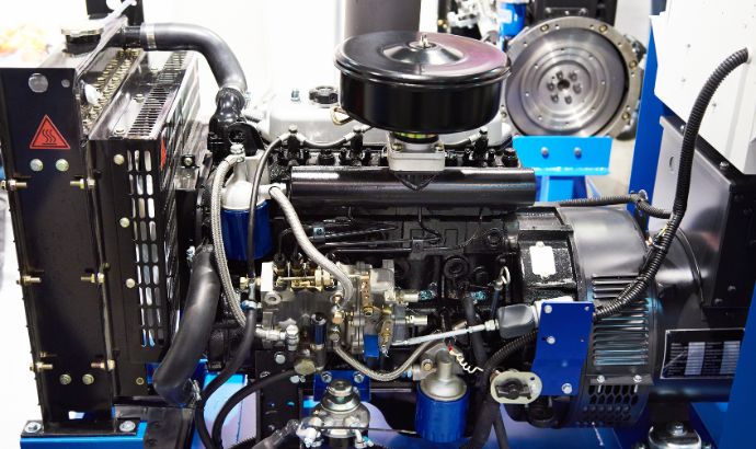
A synchronous generator is a rotating electrical machine that converts mechanical energy — supplied by a prime mover such as a steam turbine, gas turbine, diesel engine, or hydraulic turbine — into three-phase alternating current at a frequency rigidly locked to the machine’s rotational speed. It is the backbone of virtually every large-scale electrical power generation system in the world: from utility power plants to industrial cogeneration units, from hydroelectric stations to standby power installations.
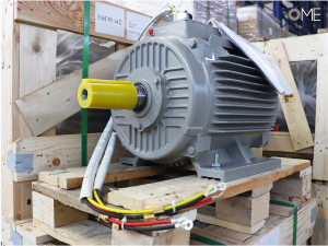
OME Motors designs and manufactures industrial synchronous generators at its Brescia, Italy facility, supplying power generation projects and industrial cogeneration systems across global markets.
This guide explains how a synchronous generator works, the difference between brushless and slip-ring configurations, and the industrial applications where synchronous generators are the standard technology.
Working principle: Mechanical to electrical conversion
A synchronous generator operates on Faraday’s law of electromagnetic induction. The machine has two main parts: a rotor carrying a magnetic field, and a stator carrying three-phase windings in which voltage is induced as the rotor field sweeps past.
In the rotor, a DC excitation current flows through a field winding (or, in permanent magnet variants, the magnetic field is provided by embedded magnets). When the prime mover rotates the rotor at design speed, the rotating magnetic field induces a three-phase AC voltage in the stator windings. The frequency of the generated voltage is directly proportional to the rotational speed and the number of pole pairs, following the equation f = (n × p) / 60, where f is the frequency in Hz, n is the rotational speed in rpm, and p is the number of pole pairs.
This rigid relationship between speed and frequency is what gives the machine its name. To generate 60 Hz output — the standard frequency in North America — a 2-pole synchronous generator must rotate at exactly 3,600 rpm. A 4-pole machine must run at 1,800 rpm, a 6-pole at 1,200 rpm, and so on. For 50 Hz output (Europe and most of the world), the corresponding speeds are 3,000, 1,500, and 1,000 rpm.
Brushless vs Slip-ring excitation
Modern industrial synchronous generators are supplied in two excitation configurations, each suited to different application requirements.
The brushless synchronous generator eliminates all sliding contacts on the main shaft. Excitation current is supplied to the rotor field winding through an auxiliary exciter — a small AC generator mounted coaxially on the same shaft — and a rotating rectifier bridge. There are no brushes, no slip rings, and no carbon dust to maintain or clean. The advantages are substantial: no periodic brush replacement, suitability for dusty or classified environments, extended maintenance intervals, and higher long-term reliability. Brushless configuration is the standard for most modern industrial and standby applications, and is the default for the OME Motors synchronous generator range.
The slip-ring synchronous generator uses brushes and slip rings to supply DC excitation from an external source. This configuration is still used on very large machines (utility power plants above 100 MW) where the external excitation system allows tighter voltage regulation and faster response to grid disturbances, and on specialized machines where the external excitation control is a design requirement.
Grid synchronization: Four conditions
Connecting a synchronous generator in parallel with an existing electrical grid — the standard operating mode in power plants and cogeneration units — requires four conditions to be met simultaneously before closing the paralleling breaker:
- Voltage magnitude of the generator must equal the grid voltage
- Frequency of the generator output must equal the grid frequency
- Phase sequence (A-B-C rotation) must match the grid
- Phase angle must be aligned within a small tolerance
Verification is performed by a synchroscope and voltmeter comparison in manual operation, or by an automatic synchronizer in modern installations. Closing the breaker when the four conditions are not met produces severe transient torques that can damage the shaft, windings, and coupling.
Once paralleled, the prime mover’s mechanical torque controls the active power delivered to the grid, while the rotor excitation current controls the reactive power — the generator can operate at leading, unity, or lagging power factor by adjusting excitation.
Alternator vs Synchronous generator: Same machine, same principle
The terms alternator and synchronous generator refer to the same fundamental machine — a rotating electrical device that produces alternating current — and are often used interchangeably in industrial literature. The term alternator is more common in automotive and low-power contexts (the alternator in a car is a small synchronous generator with permanent magnets or claw-pole excitation). The term synchronous generator is standard in industrial and power generation contexts. There is no technical distinction beyond terminology.
The distinction that does matter technically is synchronous vs asynchronous generator: an asynchronous (induction) generator uses a squirrel-cage or wound rotor and requires an existing grid to supply magnetizing current — it cannot operate as a standalone source. Synchronous generators are self-exciting (via brushless or slip-ring excitation) and can operate stand-alone or grid-parallel.
Industrial applications of synchronous generators
Synchronous generators are the dominant technology across virtually all industrial and utility-scale power generation:
- Thermal power plants — coupled to steam turbines, gas turbines, or combined-cycle configurations for baseload and mid-merit power generation
- Hydroelectric plants — coupled to Francis, Kaplan, and Pelton turbines, ranging from small run-of-river installations to large dams
- Cogeneration (CHP) plants — coupled to gas engines, gas turbines, or steam turbines in industrial facilities that need simultaneous heat and power (paper mills, refineries, chemical plants, district heating systems)
- Emergency and standby power — driven by diesel or gas engines for hospitals, data centers, industrial plants, and critical infrastructure
- Wind power generation — permanent-magnet synchronous generator variants are increasingly used in direct-drive wind turbines
- Marine and offshore power systems — shipboard main generators, offshore platform electrification
- Industrial processes with speed-critical machinery — where the rigid synchronous speed of the connected motors requires a stable grid source
For applications ranging from a few hundred kVA up to multi-megawatt installations, OME Motors supplies custom-engineered synchronous generators with the voltage, frequency, cooling, and protection specifications defined by the specific project. Related synchronous motor technology for industrial drive applications is covered in the guide to PMSM permanent magnet synchronous motors.
The OME Motors approach to synchronous generators
OME Motors manufactures industrial synchronous generators to project-specific requirements: rated power, voltage, frequency (50 Hz, 60 Hz, or 50/60 Hz), pole count, excitation type, cooling system (IC 01, IC 411, IC 611, IC 81W water-to-air), degree of protection, and full custom certification packages for global project delivery. Each machine is designed and built at the Brescia facility with routine and type tests performed on-site.
To discuss a project specification or request an engineering evaluation, contact the OME Motors team or explore the full electric motor and generator range.
















































 Headquarter - Via Camillo Golgi 8 - 25064 GUSSAGO (BS)